Vocational Scenario or Context
The use and application of mechanical systems is an essential part of modern life. The design, manufacture and maintenance of these systems are the concern of engineers and technicians who must be able to apply a blend of practical and theoretical knowledge to ensure that systems work safely and efficiently. Science underpins all aspects of engineering and a sound understanding of its principles is essential for anyone seeking to become an engineer. Having completed learning outcome LO8.1 of Mechanical Principles of Engineering Systems in your course at Newham College, you are required by your employer to demonstrate your understanding in effects of loading in static engineering systems particularly effects of mechanical force on solids. To do this complete the tasks below.
Task 1
Statics
Calculate the magnitude, direction and position of the resultant force and turning moment about point for the system of forces acting on the bridge support plate shown in figure 1. What would be the equilibrant force and its direction? P1

Figure 1 Bridge support plate
Task 2
Simply supported beam Calculate the support reactions for the roof beam shown figure 2. The uniformly distributed load (UDL) is across the whole length of the beam. P2 Figure 2 Roof beam

Figure 2 Roof beam
Task 3
- Component subjected to direct uniaxial loading
The rectangular steel bar, figure 3 is part of a static test rig and extends under a tensile load of kN. If the elastic modulus for the steel material is 208 GN/m2, calculate:
- the stress in the bar,
- the resulting strain, and
- the extension of the bar. P3

- Component subjected to shear loading
A rivet which has a diameter D mm is being used to hold together the sides of a storage vessel and is subject to the loadings shown in the figure 4. Calculate:
- the resulting shear stress
- the resulting shear strain if the shear modulus for the rivet material is 79 GN/m2. P3

Figure 4 Loads on a rivet holding together a storage vessel
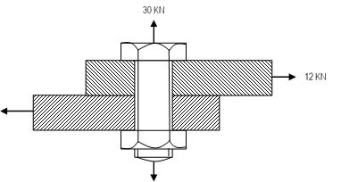
- The diagram in figure 5 shows the section through part of a car trailer and the corresponding loading. The failure criteria for the diameter high tensile bolt shown is:
Calculate the maximum permissible factor of safety for the working conditions detailed. M1

P3 calculate the induced direct stress, strain and dimensional change in a component subjected to direct uniaxial loading and the shear stress and strain in a component subjected to shear loading
M1 calculate the factor of safety in operation for a component subjected to combined direct and shear loading against given failure criteria
Are You Looking for Answer of This Assignment or Essay
The post Pearson BTEC Level 3 Unit 8 Mechanical Principles of Engineering Systems : Statics, Assignment, UK appeared first on Students Assignment Help UK.